This post is part of the Rack Box Project series.
Get more digital outputs on your I/O device with a multiplexer, 3 outputs turned into 7.
Table of contents
Details
A common problem, at least for me, when using I/O devices is running out of ports. When I was using the parallel I/O device in my rack box project, I ran out of outputs. I solved that by making this output extender. It’s quite simple; it uses a multiplexer circuit to multiplex 3 outputs and turn them into 7. It does have some limitations though…
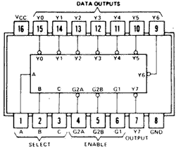
I used the 3-line to 8-line decoder/demultiplexer circuit 74HC138. It has, as implied by the name, 3 inputs and 8 outputs. The outputs are inverted, meaning they are low when turned on. That was perfect for my purpose, since all my modules had open collector outputs, which operates the same way.
There are however some limitations to this approach; multiplexing the outputs means that only one of the multiplexer outputs can be on at any given time. For some applications this may be a problem, but it wasn’t for me; since I only used the outputs to send signal pulses to other modules.
If I wanted to pulse an output on the multiplexer I needed to turn on 1, 2 or 3 of the outputs on my parallel I/O device. The outputs on the 74HC138 multiplexer is rated for 25 mA, which was more than enough for my needs.
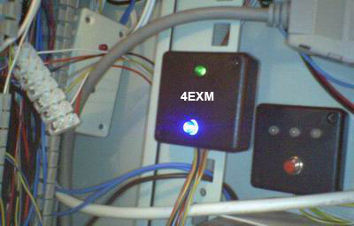
Green LED shows system in standby, while the blue LED is server time-out alarm.
Function table
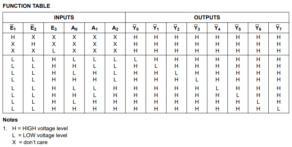
This is function table for the 74HC138 multiplexer, it explains the relation between the inputs and outputs. Looking at it we can see that in order to turn off all outputs we need to set Enable 3 low. So you can either:
- Use E3 and the inputs to get 8 outputs, that gives a input/output ratio of 2.
- Or use only the inputs and get 7 outputs, which gives a input/output ratio of 2.33.
So that was what I did; I used only the three inputs, set Enable 3 constantly high and disregarded output 1.
Binary values
| Out | In 1 | In 2 | In 3 | Binary value |
|---|---|---|---|---|
| 1 | 1 | 0 | 0 | 1 |
| 2 | 0 | 2 | 0 | 2 |
| 3 | 1 | 2 | 0 | 3 |
| 4 | 0 | 0 | 4 | 4 |
| 5 | 1 | 0 | 4 | 5 |
| 6 | 0 | 2 | 4 | 6 |
| 7 | 1 | 2 | 4 | 7 |
D-Sub 15-pin
- 0V
- 5V
- Input 1
- Input 2
- Input 3
- Output 1
- Output 2
- Output 3
- N/A
- Server time-out alarm LED (Main monitoring unit)
- Status-LED +
- Output 7
- Output 6
- Output 5
- Output 4
Parts list
- 1 × D-sub soldering cups, 15 pin male
- 1 × Demultiplexer, 3 -> 8, 74HC138
- 1 × DIL socket, 16-pin, 7.62mm
- 1 × Enclosure, plastic (1551), 50x50x20mm
- 1 × LED 5mm clear, Blue, 4.9V, 20mA, 350mcd, 12°
- 1 × LED 5mm coloured clear, Green, 2.1V, 20mA, 30mcd, 10°
- 1 × LED holder 5mm, RTC51, black plastic
- 1 × LED lens 5mm, CLF 280, Blue
- 5 × Resistor, carbon film, 0.25W, 330 Ω, 5%
- 3 × Resistor, carbon film, 0.25W, 10 kΩ, 5%
Last commit 2024-04-05, with message: Tag cleanup.
Rack Box Project series
- Parallel port I/O module
- Power supply and fuse monitoring module, AVR
- Monitored fuse box, 6 channels
- Stack lights and horn controller — with AVR
- Mute and light controller for the Rack box — AVR module
- Monitored fuse box, 4 channels
- Module heartbeat monitor, 6 inputs — AVR
- Controller for lights and relays — AVR driven
- Emergency power off controller — controlled by 555 timers
- Fan controller with LCD — AVR powered
- Sound alarm control unit — AVR module
- Multiplexer output extender
- Multi-purpose AVR module
- Electric heater and timer controller — AVR
- Module heartbeat monitor, 15 inputs — LCD and AVR
- Serial port I/O module with 11 inputs — AVR
- Serial port I/O module with 9 in and outputs — AVR
- Serial interface for emergency power off — AVR
- Status panel for the Rack box project
- Intruder alarm system controller — AVR
- Serial port I/O module with 15 inputs — AVR
- Serial interface module, with analog and digital I/O — AVR
- The rack box project — an overview