This post is part of the Rack Box Project series.
Control three lights or relays, with toggle switches and status LEDs. Uses an AVR ATtiny2313 microcontroller.
Table of contents
Details
This was one of the first modules installed in the rack box project, I used it to control some lights and the sub-woofer in my old apartment. It had three operator panels; in the living room, entryway and as part of the status panel for Rack box project. Momentary switches were used to either show the status, or if held for more than one second, toggle the outputs.
The goal of this lights and relay controller was very simple; allow control of the lights and sub-woofer from more than one location and by using automation. I could send trigger signals to this controller using the parallel I/O module.
When receiving an switch input pulse longer than one second, the controller would toggle that respective output and show the current state on the status LED. This made it very easy to connect multiple switches, since they didn’t need to know anything about the current state.
For automation purposes however the output status also had to be read, either using the status signal for that output, or the output itself. The output state was stored in EEPROM, and restored when the module was powered up.
The status LEDs were only enabled when a switch input was active, and two seconds after. So during normal operation all status LEDs would be turned off. That way the current state could be checked by an switch input pulse shorter than one second, without toggling the output.
In my old apartment; I used this module to control:
- Living room lights
- Sound system sub-woofer
- Computer desk lights
Delayed all-off
45 seconds after the delayed all-off input was triggered; all outputs were turned off. During that countdown all the status LEDs were flashing, and the flashing pattern speed increased for the last 10 seconds. By activating any of the switch inputs the all-off countdown was aborted.
Auto light
The auto light input was used by the Intruder alarm system controller to turn on the lights when someone enter the apartment. The IR sensor input were used so that the lights would stay on as long as there was movement. Two minutes after the movement stopped the lights would turn off.
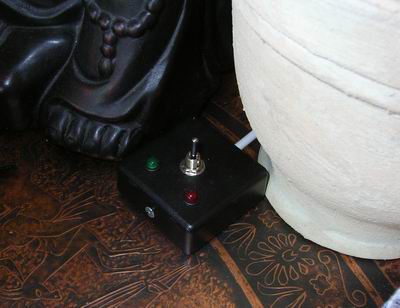
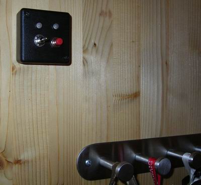
Operator panels
I had three operator panels;
- In the living room, used to control the living room lights and sub-woofer.
- In the entryway, used to control the living room and desk lights, and activate the delayed all-off function.
- On the computer desk, as part of the status panel for Rack box project, this could control all three outputs.
By using two-way momentary toggle switches, I could control two outputs using the same switch.
Relays
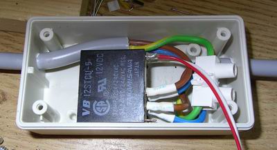
220VAC relays were used to turn the lights and sub-woofer on and off. I made short extension cables though the relay, and thin signal cables going from the controller module activated the relays.
Control:
- Lamp living room
- Subwoofer
- Lights and printer on desk
- Lights living room (handled by Multi-purpose module 1)
Video
The lights and relay controller appears at 1:00. First the sub-woofer is turned on, then the living room lamp.
I/O
Inputs
- Switch channel 1
- Switch channel 2
- Switch channel 3
- IR Sensor (from Multi-purpose module 1)
- Lights out 45 sec
- Auto light 2 min
- Lights out
Outputs
- Relay 1
- Relay 2
- Relay 3
- LED 1
- LED 2
- LED 3
- Life-light
- Life-signal to Module heartbeat monitor
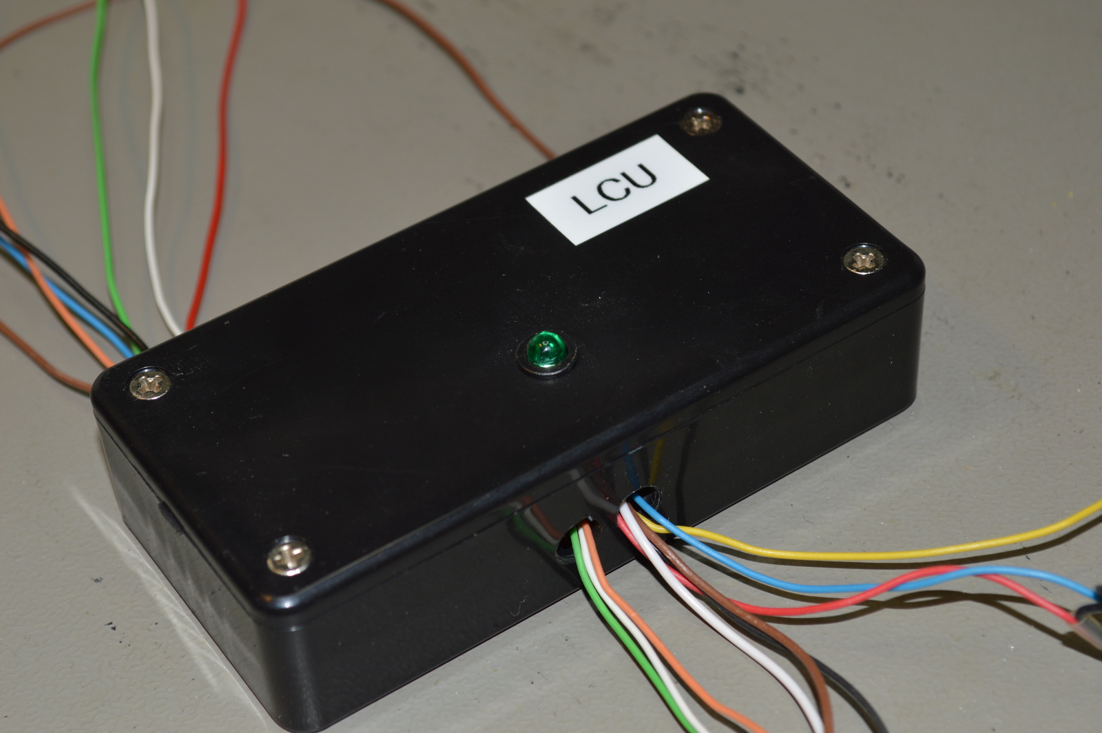
Wires
Top
- Red +5V
- Black 0V
- Brown Life-signal
- White IR sensor
- Green Lights out 45 sec
- Orange Auto light 2 min
- Blue Lights out
Bottom
- White Switch 1
- Orange Switch 2
- Green Switch 3
- Yellow Relay 1
- Blue Relay 2
- Red Relay 3
- Brown LED 1
- Black LED 2
- White (clear) LED 3
Source code
- Bascom-AVR source is available in a git repository:
- https://github.com/thomasjsn/AVR-Lights-and-relay-controller
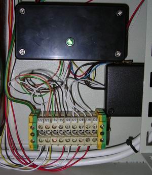
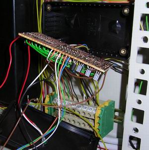
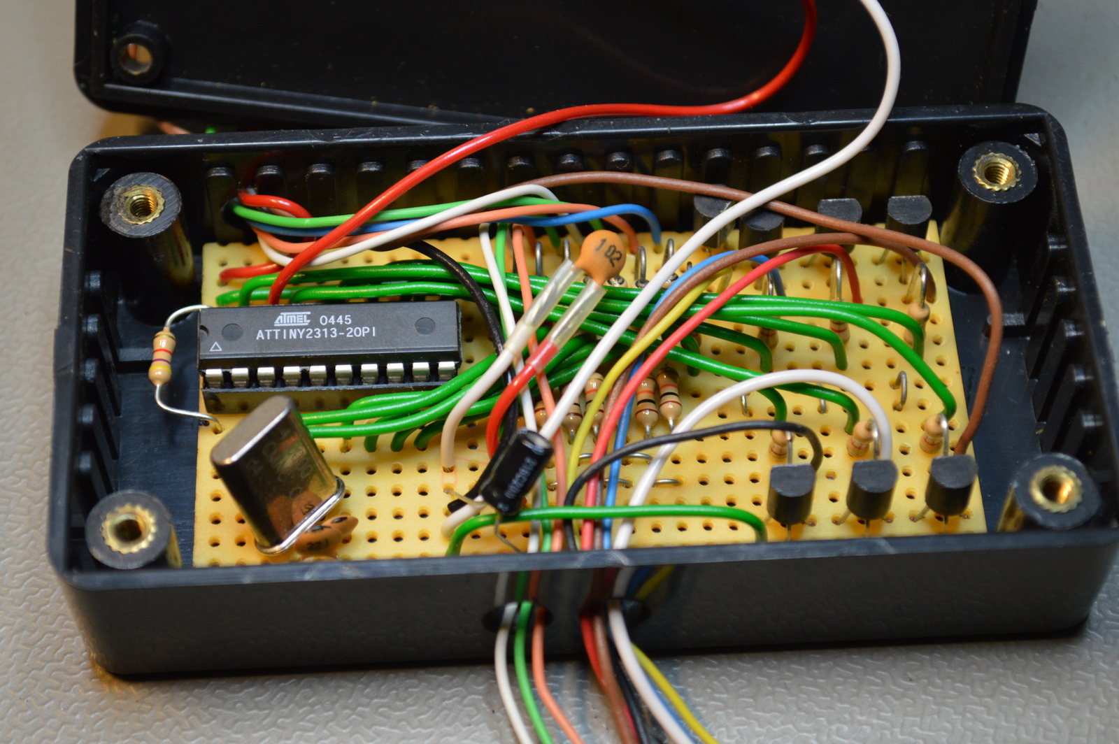
Photos
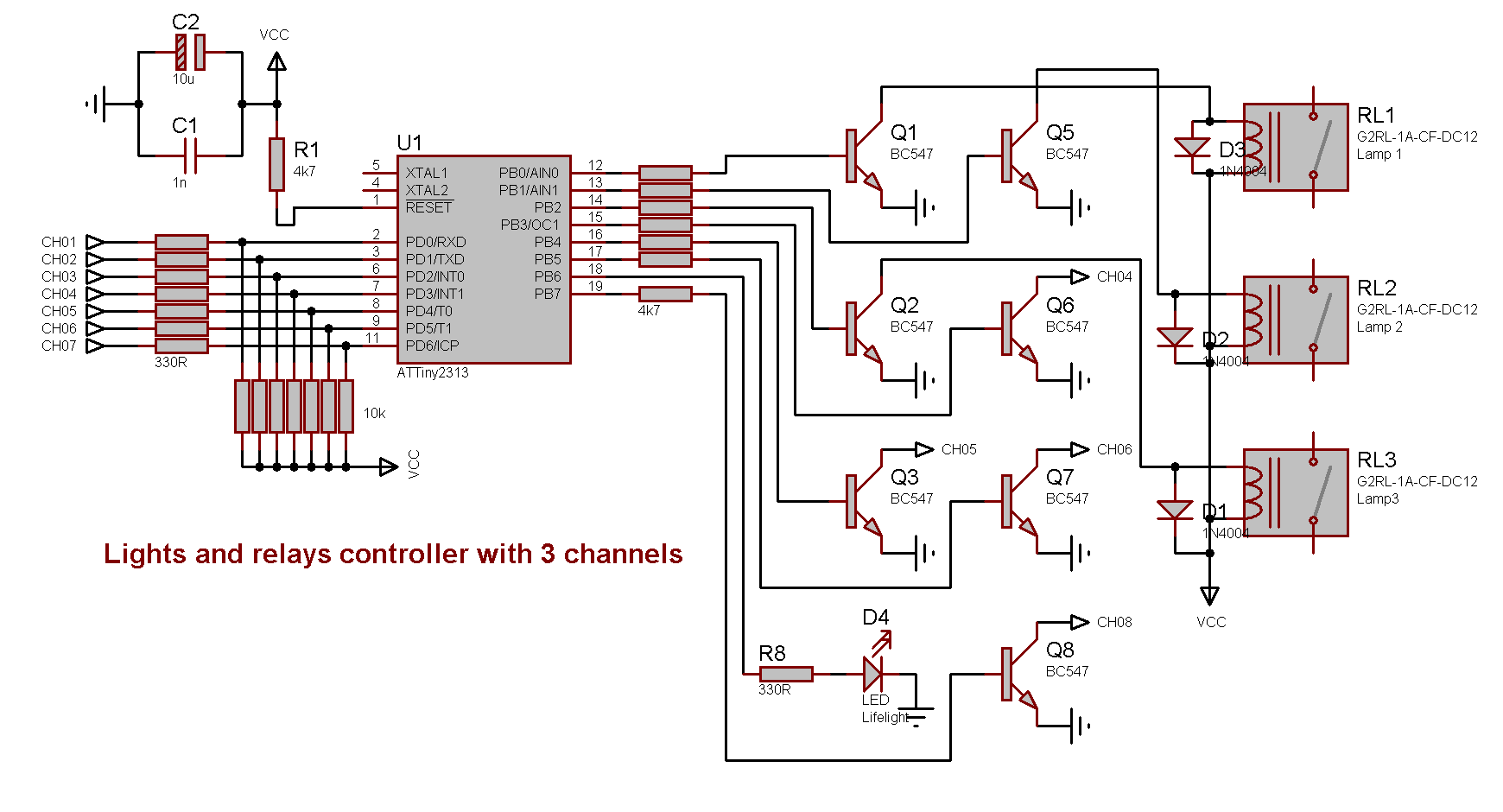
Schematic drawing
Parts list
- 1 × AVR ATtiny2313-20PU, DIL-20, 20 MHz, 18 I/Os
- 1 × Capacitor, aluminium electrolytic, 10 µF, 25V
- 2 × Capacitor, ceramic, 22 pF, 100V
- 1 × Capacitor, ceramic, 1 nF, 100V
- 1 × DIL socket, 20-pin, 7.62mm
- 1 × Enclosure, plastic (1591), 100x50x25mm
- 1 × LED 5mm coloured clear, Green, 2.1V, 20mA, 30mcd, 10°
- 1 × LED holder 5mm, RTC51, black plastic
- 32 cm2 PCB, stripboard, 100x160mm, 160cm2
- 1 × Quartz crystal oscillator, 4 MHz
- 8 × Resistor, carbon film, 0.25W, 330 Ω, 5%
- 8 × Resistor, carbon film, 0.25W, 4.7 kΩ, 5%
- 7 × Resistor, carbon film, 0.25W, 10 kΩ, 5%
- 7 × Transistor, NPN, 100 mA, 45V, 0.5W, BC547B
Last commit 2023-02-05, with message: Add series for the rack box project.
Rack Box Project series
- Parallel port I/O module
- Power supply and fuse monitoring module, AVR
- Monitored fuse box, 6 channels
- Stack lights and horn controller — with AVR
- Mute and light controller for the Rack box — AVR module
- Monitored fuse box, 4 channels
- Module heartbeat monitor, 6 inputs — AVR
- Controller for lights and relays — AVR driven
- Emergency power off controller — controlled by 555 timers
- Fan controller with LCD — AVR powered
- Sound alarm control unit — AVR module
- Multiplexer output extender
- Multi-purpose AVR module
- Electric heater and timer controller — AVR
- Module heartbeat monitor, 15 inputs — LCD and AVR
- Serial port I/O module with 11 inputs — AVR
- Serial port I/O module with 9 in and outputs — AVR
- Serial interface for emergency power off — AVR
- Status panel for the Rack box project
- Intruder alarm system controller — AVR
- Serial port I/O module with 15 inputs — AVR
- Serial interface module, with analog and digital I/O — AVR
- The rack box project — an overview