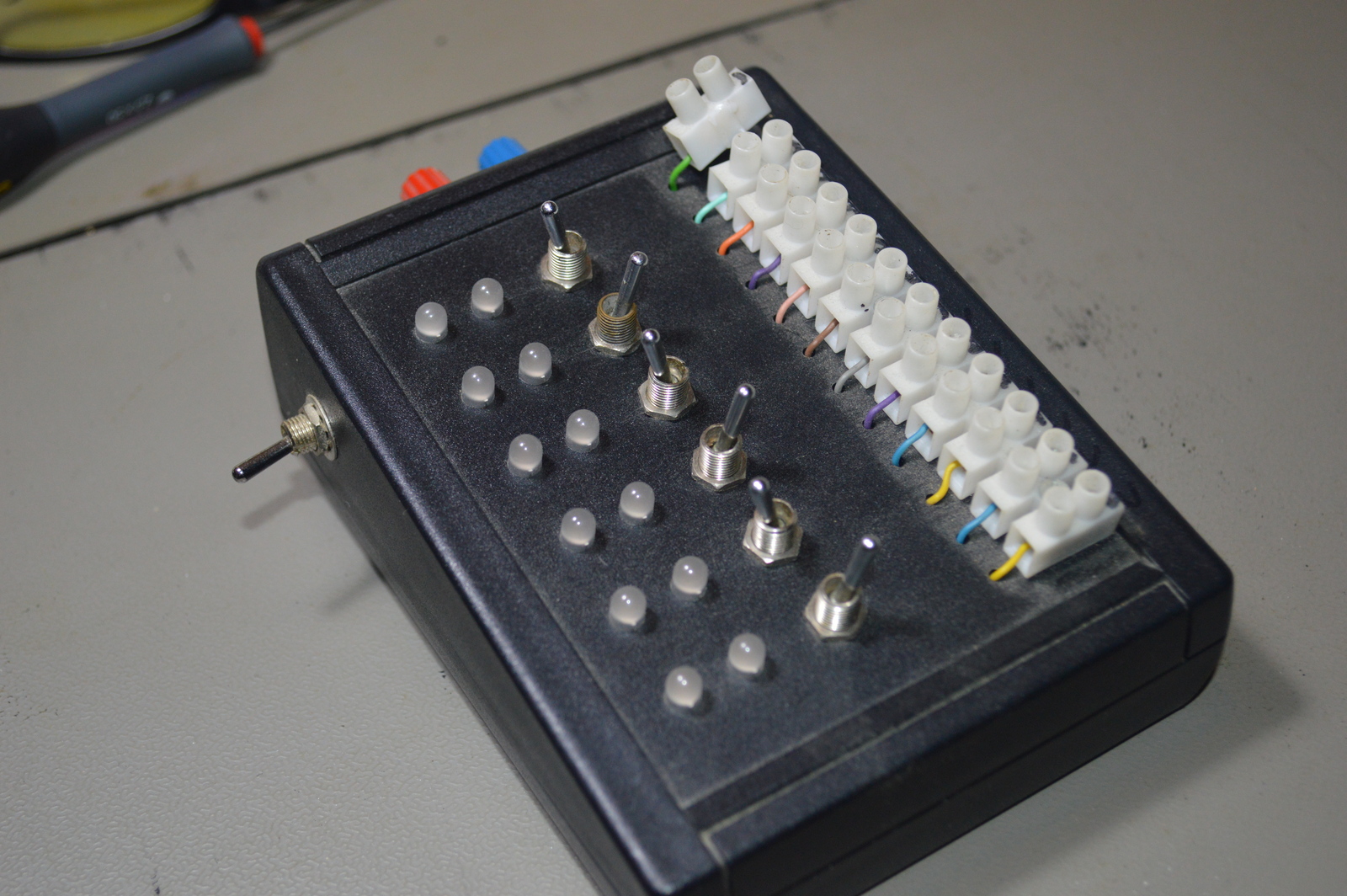
A simple box with LEDs and switches to test digital inputs and outputs.
Table of contents
Details
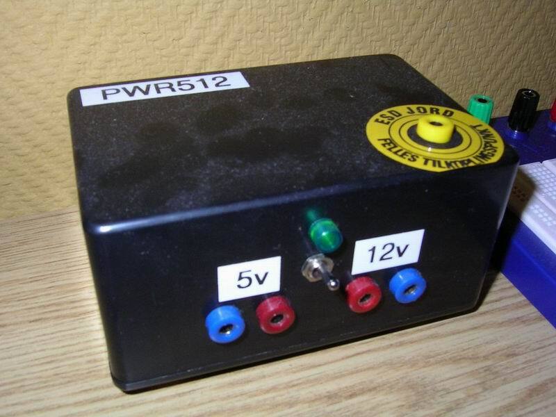
This unit is used for simulating inputs and outputs when a AVR module is complete, before installation. The module is power by a 5/12V power supply through plugs in the back. Every input has two LEDs, one green and one red. If both are lit this means that the output is not active. If the green LED is lit it’s a positive signal on the input, and red if it’s negative. The outputs are connected to small toggle switches, and can be used N.O or N.C The switch on the left reverses the polarity of the outputs.
I/O
- LED 1
- LED 2
- LED 3
- LED 4
- LED 5
- LED 6
- Switch 1
- Switch 2
- Switch 3
- Switch 4
- Switch 5
- Switch 6
Photos
Parts list
- 1 × Banana socket, panel, BIL 20, 4mm blue
- 1 × Banana socket, panel, BIL 20, 4mm red
- 1 × Banana socket, panel w/binding post, PK4-T, 4mm blue
- 1 × Banana socket, panel w/binding post, PK4-T, 4mm red
- 1 × Desk casing, black, 100x130mm
- 12 × LED 5mm, Red/Green, 2.0 2.1V, 10mA, 100 63mcd, 30°
- 12 × Resistor, metal film, 0.6W, 1 kΩ, 1%
- 7 × Switch, toggle, 1-pole, micro, on-on
- 12 × Terminal block, screw, 2.5 mm
Last commit 2021-03-22, with message: publish old posts