This post is part of the Rack Box Project series.
Emergency stop controller for the rack box project. Uses two 555 timers.
Table of contents
Details
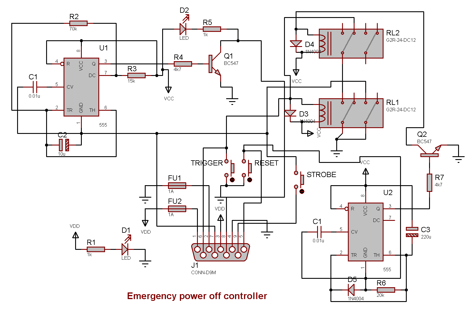
This module will cut the main power to the Rack box if emergency power off is activated. The module is powered by a separate 12V supply; the emergency supply.
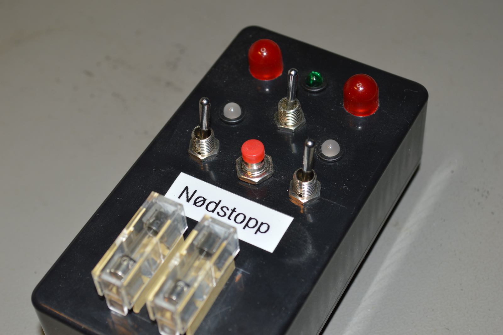
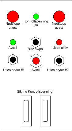
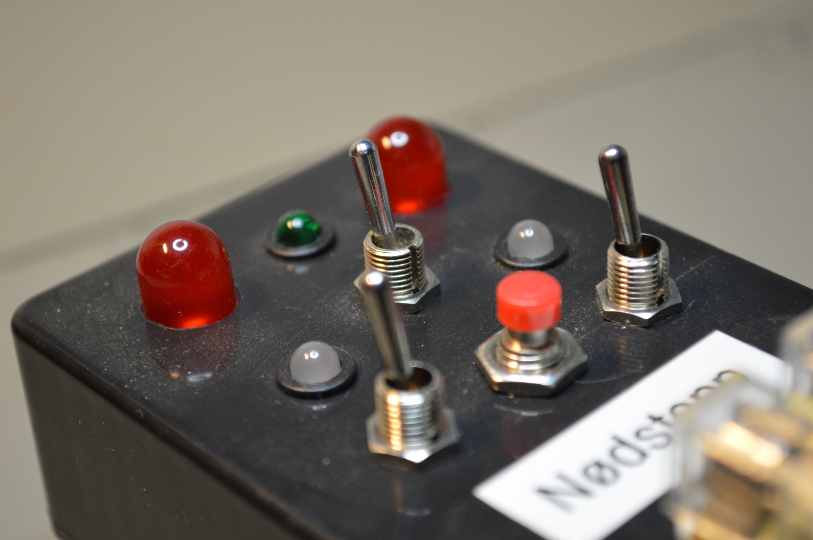
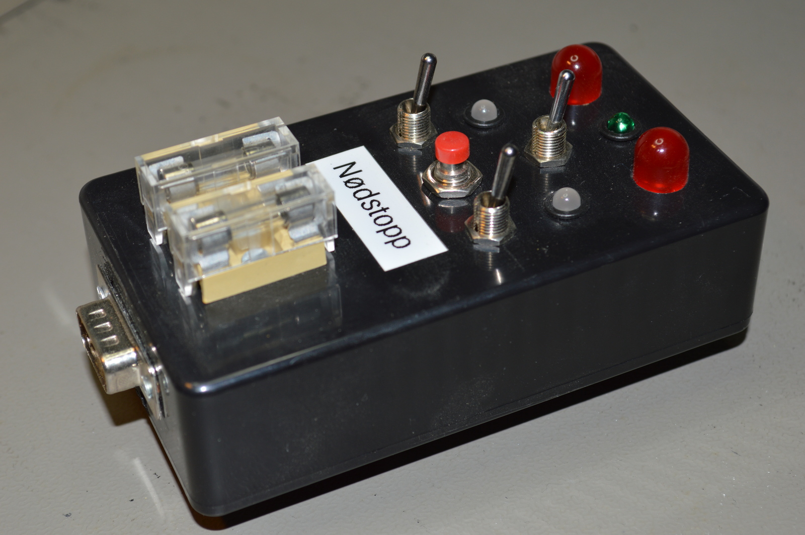
Main fuses are located on the module front, a green LED shows that voltage is present. If one of the fuses should burn out Main monitoring unit will signal a supply error.
Two big red LEDs flash when the emergency power off is activated. An alarm output, used for a strobe, is also activated, but this can be disabled with a switch.
From the module front one can trigger and reset the emergency power off, this can also be done from the Rack status panel. Or with Serial I/O system, using the Digital emergency interface module.
The module uses two 555 timers, one makes the big red LEDs to flash when triggered. The other is used as a reset delay, requiring the reset button to be pressed for five seconds.
Video
Quick demo showing the operation of the emergency power off controller. First triggering, then resetting the emergency power off.
At 2:00 the rack box emergency power off is triggered and everything shuts down — then reset.
D-Sub 9-pin
- 12v+ in
- 12v- in
- 12v+ out
- 12v- out
- Reset switch input
- Trigger emergency input
- Emergency relay output
- Emergency LED output
- Emergency strobe output
Photos
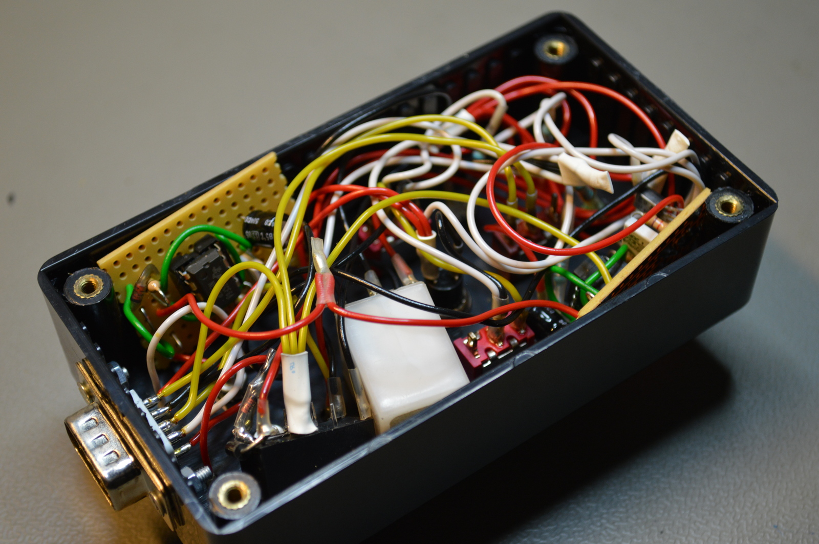
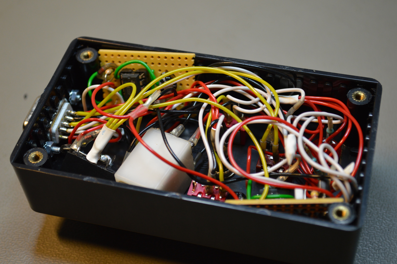
Schematic drawing
Parts list
- 2 × Capacitor, aluminium electrolytic, 47 µF, 25V
- 2 × Capacitor, metallized polyester foil, 10 nF, (0.01 µF)
- 1 × D-sub soldering cups, 9 pin male
- 2 × DIL socket, 8-pin, 7.62mm
- 2 × Diode, rectifier, 1 A, 400V, 1N4004
- 2 × Diode, small signal, 1N4148/Ph
- 1 × Enclosure, plastic (1591), 112x62x31mm
- 2 × Fuse 5x20 mm, 2 A, fast-acting
- 2 × Fuse holder, open, PCB, 5x20mm
- 2 × Fuse holder, open, PCB, Protective cover
- 2 × LED 10mm, Red, 2.0V, 20mA
- 1 × LED 5mm coloured clear, Green, 2.1V, 20mA, 30mcd, 10°
- 2 × LED 5mm, Red/Green, 2.0 2.1V, 10mA, 100 63mcd, 30°
- 3 × LED holder 5mm, RTC51, black plastic
- 2 × Mounting bracket, DIN rail, Plastic
- 32 cm2 PCB, stripboard, 100x160mm, 160cm2
- 2 × Relay, 2 CO, HJR1-2C, 12 VDC, 1A 120V, PCB
- 4 × Resistor, carbon film, 0.25W, 4.7 kΩ, 5%
- 1 × Resistor, carbon film, 0.25W, 100 kΩ, 5%
- 5 × Resistor, metal film, 0.6W, 1 kΩ, 1%
- 1 × Switch, push-button, 1-pole, 1A, 50VAC, off-(on)
- 2 × Switch, toggle, 1-pole, micro, on-(on)
- 1 × Switch, toggle, 1-pole, micro, on-on
- 2 × Timer IC, NE 555, 0/+70 °C, DIL8
- 2 × Transistor, NPN, 100 mA, 45V, 0.5W, BC547B
Last commit 2023-02-05, with message: Add series for the rack box project.
Rack Box Project series
- Parallel port I/O module
- Power supply and fuse monitoring module, AVR
- Monitored fuse box, 6 channels
- Stack lights and horn controller — with AVR
- Mute and light controller for the Rack box — AVR module
- Monitored fuse box, 4 channels
- Module heartbeat monitor, 6 inputs — AVR
- Controller for lights and relays — AVR driven
- Emergency power off controller — controlled by 555 timers
- Fan controller with LCD — AVR powered
- Sound alarm control unit — AVR module
- Multiplexer output extender
- Multi-purpose AVR module
- Electric heater and timer controller — AVR
- Module heartbeat monitor, 15 inputs — LCD and AVR
- Serial port I/O module with 11 inputs — AVR
- Serial port I/O module with 9 in and outputs — AVR
- Serial interface for emergency power off — AVR
- Status panel for the Rack box project
- Intruder alarm system controller — AVR
- Serial port I/O module with 15 inputs — AVR
- Serial interface module, with analog and digital I/O — AVR
- The rack box project — an overview