AVR is a series of microcontrollers from Atmel. Fitted with A/D converters, comparators, timers, interrupts, internal oscillator, and more. Flash memory is used for the main program, SDRAM for variables and EEPROM for values that need to be saved through a power loss. Cheap, fast and easy make them perfect for home automation projects.
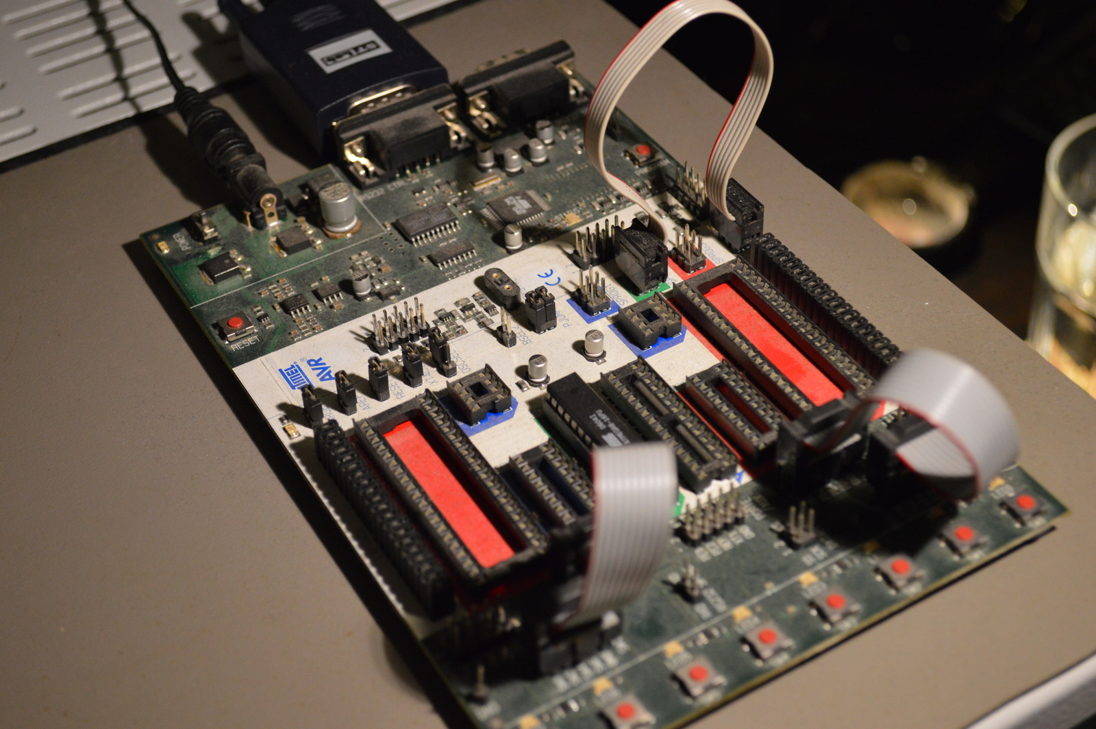
Speeds up to 20 Mhz, USART (e.g., RS-232, RS-485) and low power consumption are some other benefits. A starting kit such as the STK500 is a good basis, with this you can test and program a variety of devices.
Table of contents
Getting started
Programming
There are a lot of different IDEs and compilers available, here is a few of them:
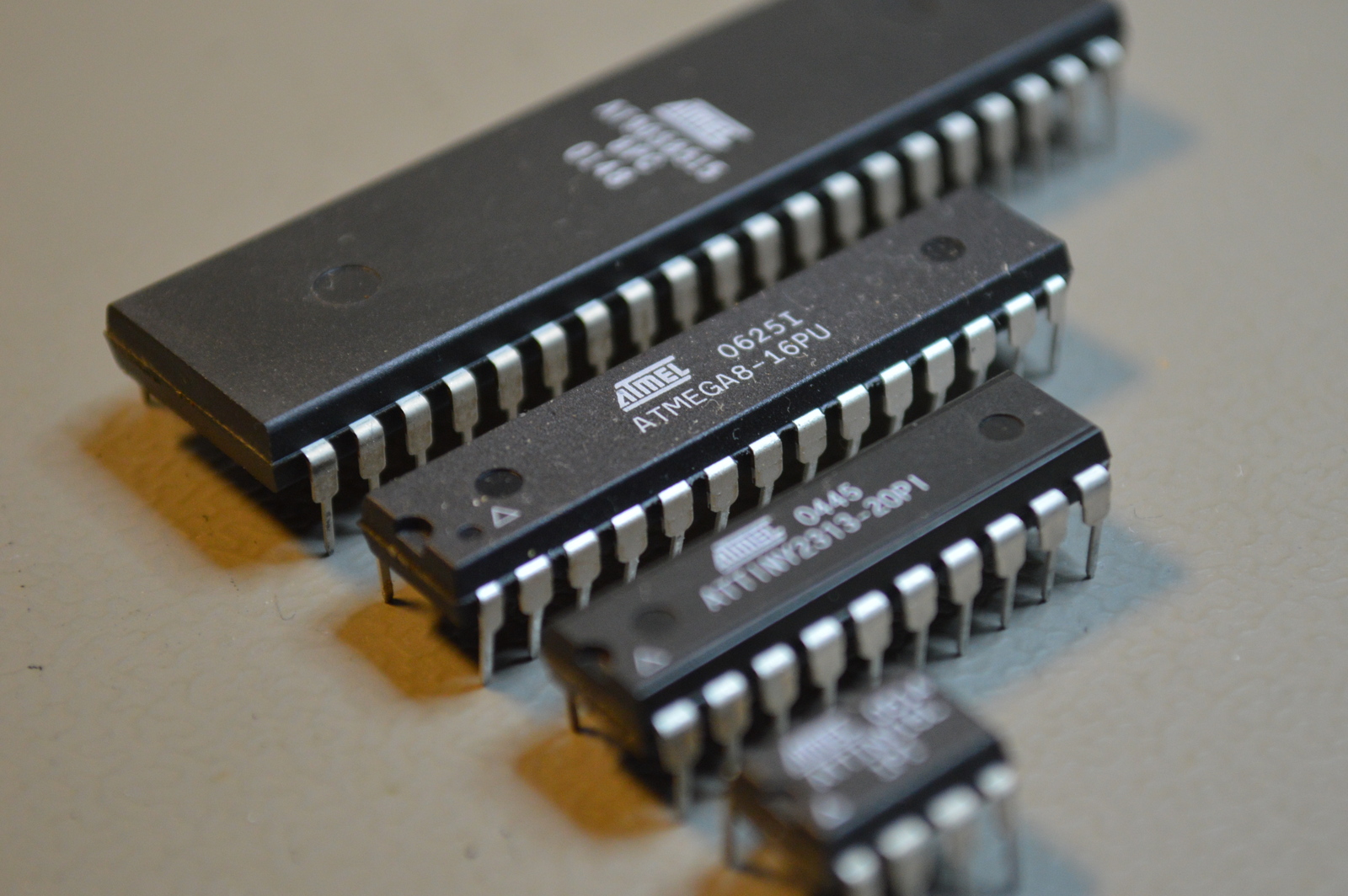
Devices
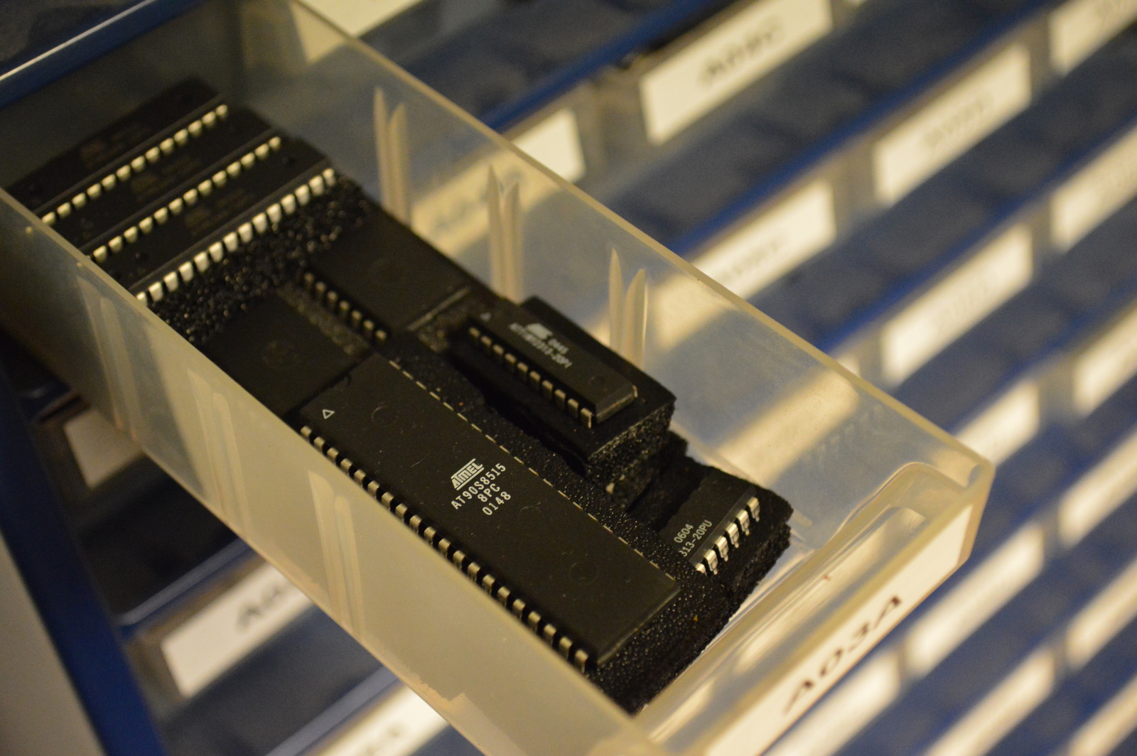
These are some of the devices I most commonly use, for the complete list see Atmels device list:
- ATmega8
- ATmega8515
- ATtiny15
- ATtiny2313
- ATtiny26
Basic circuit
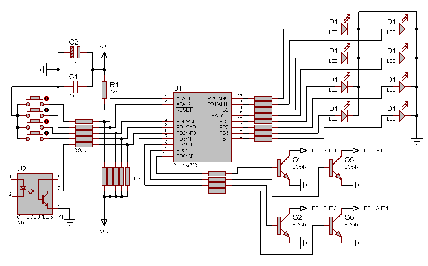
This basic circuit has 7 inputs and 8 outputs and uses an ATtiny2313 with internal oscillator. That is the maximum capacity for this device if you don’t count PA.0, PA.1, and PA.2, which is typically used for a crystal oscillator and a reset switch.
Power
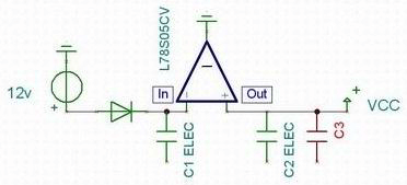
Most AVR microcontrollers run on 5 volts, which you can easily get by using a voltage regulator and a couple of capacitors. I usually use 47 µF for C1 and C2. A voltage regulator like the L78S05CV can deliver 2 amps and have a maximum input voltage of 35 volts. Remember to mount a heat-sink, especially with high input voltage or high load.
External crystal
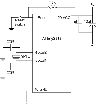
If you are going to use an external crystal oscillator, it must be connected between XTAL1 and XTAL2 with a 22pF capacitor to GND on both sides. Remember to set the fuse bits according to your oscillator, and if you are going to use serial communication; pick a frequency that works with your baud rate.
I/O
Digital inputs
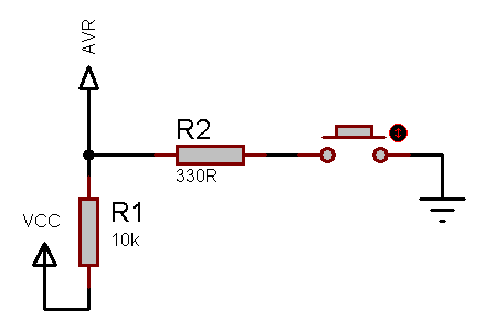
If your input has a pull-up resistor, it is pulled high when not active. So you need to pull it down (low) to trigger it, meaning that it is triggered by ground. Note that this also inverts your inputs, so you need to handle that in your programming.
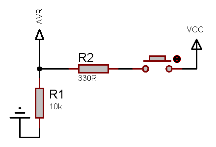
When your input has a pull-down resistor, it is pulled low when not active and you activate it by pulling it up (high).
Analog inputs
Analog inputs don’t require pull-ups or pull-downs, they measure the input voltage. The value of the input is relative to the AREF (analog reference) pin, meaning that if this pin has 5 volts, and your input has 2.5 volts, you will get a value of 512 (half of 1023, which is the maximum of a 10 bit ADC). Remember to power the ADC by connecting it’s AVCC and GND pins to power.
To measure higher voltages than the input can handle; you can use a voltage divider, this divides the voltage down by using two resistors. And for restive sensors, you can use a Wheatstone bridge.
Digital outputs
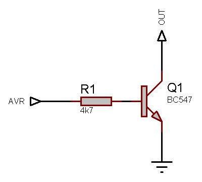
You can power an LED (20 mA) of the AVR output without any additional components, but any more than that and it’s going to need some help. For this we use transistors, a bipolar NPN transistor is a good choice. You need a resistor on the base pin; otherwise too much current passes through the transistor, and it will break.
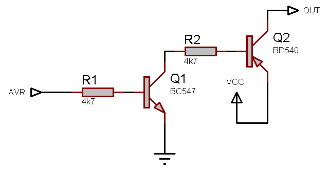
If you are going to drive some heavy stuff, a small bipolar transistor is not going to be enough. You need a power transistor, but these do not have the same amount of amplification, so it’s a good idea to place it after your small bipolar transistor.
Components
LEDs
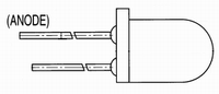
You will pretty much always need a resistor when powering LEDs. Here is a useful tool for calculating the value of that resistor: LED Resistor Calculator.
Useful reading
Transistors
Useful reading
Relays
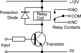
When connecting a relay to a digital output, it must have a protection diode; this prevents a power surge from flowing back into the input when the relay releases. This surge can cause the microcontroller to restart; it may even break the output.
Diodes
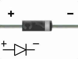
Electricity only flows one way through a diode, remember that it also has a voltage drop in the forward direction.
Useful reading
Serial
Getting your AVR device to communicate over a serial line opens up a whole new world of opportunities, and is totally badass! However; to do that we need some additional components to get our signal levels right. I’ve added a simple schematic for RS-232 (standard computer serial port) and RS-485 (multidrop communication over long wire spans).
RS-232
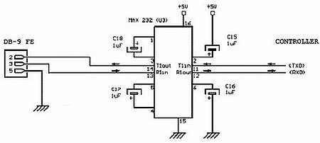
With this, you can communicate with your AVR device from your computer using the serial port, which is cool.
RS-485
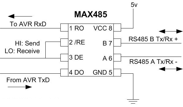
Now; with this, you can build a whole network of AVR devices operating on the RS-485 network, very cool! You will need to handle the addressing in your application though.
Now you are ready for some serious AVR projects! 🙂
External links
- AVR Freaks (AVR community with forums, projects and much more)
- SparkFun tutorial: Voltage, Current, Resistance, and Ohm’s Law
Last commit 2024-04-05, with message: Tag cleanup.